LibreCube Board Specification
This page defines the normative specification of LibreCube boards. These boards are used in stacked configuration and typically embed system components or entire subsytems (for example, a power system) or larger sensors and actuators. All LibreCube board projects must follow this specification.
The reason for defining such a board specification is to enforce a consistent and modular design of LibreCube elements. Much of this specification is inspired by the typical design of CubeSat boards, which however was never formally defined. This is quite a paradox because the success of the CubeSat program is clearly due to its standardized form factor. The internal electronic boards were never specified by the CubeSat program, which has led to many incompatible CubeSat boards, even among vendors. This shows that it is extremely important to define a formal specification of such boards.
Board Template
You can use the template board as starting point for your board development. It contains FreeCAD (for structural projects) and KiCAD designs (for PCB projects) and adheres to the requirements defined on this page.
Mechanical Specification
Board Layout
The board shall have a rectangular shape with dimension of 95.89 mm x 90.17 mm and thickness of 1.57 mm (standard PCB FR4 thickness).
The origin of the coordinate system shall be placed on the bottom left corner with X and Y axis in the directions as shown in Figure 1, and Z axis in the direction to complete a right-handed coordinate system.
The board shall have cutouts on its four edges as shown in Figure 1. Specifically, the cutouts shall span the following rectangles:
- bottom: (36.07, 0) to (56.39, 2.92)
- top: (36.07, 92.97) to (56.39, 95.89)
- left: (0, 37.81) to (2.92, 58.08)
- right: (87.25, 37.81) to (90.17, 58.08)
All corners of the board shall be rounded with a radius of 1.2 mm.
Four mounting holes with hole diameter of 3.18 mm and a pad diameter of 6.35 mm shall be located at position (5.08, 5.08), (85.09, 5.08), (8.89, 90.81), and (82.55, 90.81).
A total of 104 pin holes shall be provided, in a grid of 4×26 as shown in Illustration 1. Each hole shall be of diameter 40 mil (1.016 mm) and with a pad of 68 mil (1.7272 mm). The pitch (distance) between pin hole centers shall be 100 mil (2.54 mm). The most bottom left pin center shall be located at (13.97, 83.19).
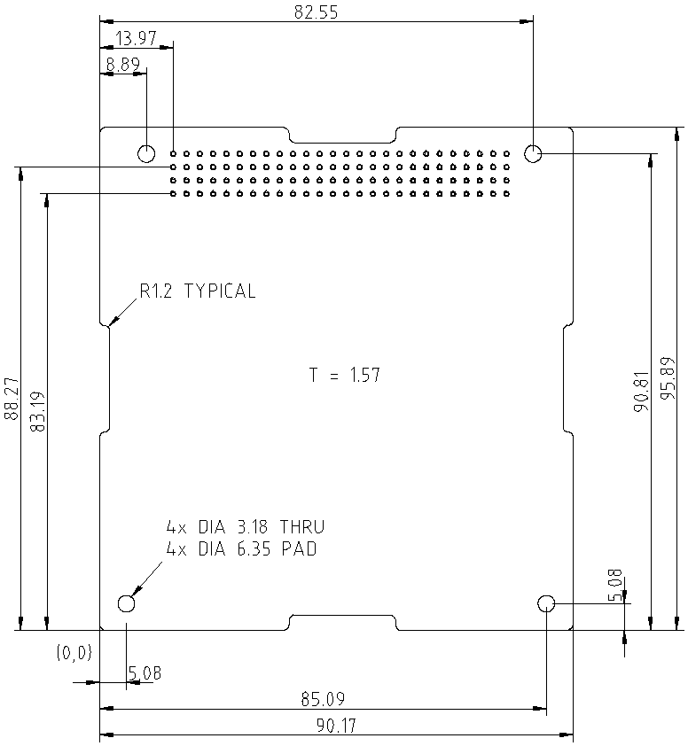
Figure 1: Board dimensions
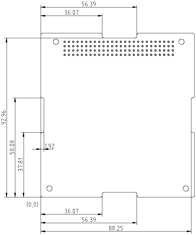
Figure 2: Dimensions of the cutouts
Board Stacking
Spacing between boards is 16 mm.
The preferred side to mount components is the top side (A).
Components shall not exceed a height of 8.76 mm above the top side (A).
Components shall not exceed a height of 4.83 mm below the bottom side (B).
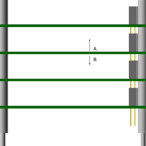
Figure 3: Board stacking
Components
- Connector: SAMTEC ESQ-126-39-[P]-D and ESQ-126-39-[P]-S or compatibles. The plating option [P] may be either gold or tin.
- Standoff: M3x16mm hex standoff
Electrical Specification
The naming of the headers (H1 and H2) and the pin numbering is shown in Figure 4.
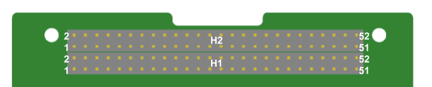
The allocation of the pins of the two headers is as shown in Figure 5, with more details in the table below. All pins not allocated are to be used freely.
Figure 4: Connector pin numbering
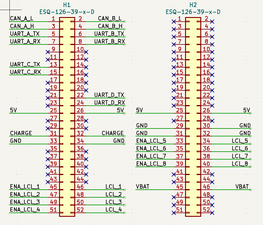
Figure 5: Electrical allocations of connector pins
Connector H1
| Pin | Name | Description |
|---|---|---|
| 1 | CAN_A_L | Nominal CAN Bus (Low Signal) |
| 2 | CAN_B_L | Redundant CAN Bus (Low Signal) |
| 3 | CAN_A_H | Nominal CAN Bus (High Signal) |
| 4 | CAN_B_H | Redundant CAN Bus (High Signal) |
| 5 | XXX | To be written |
| 6 | XXX | To be written |
| 7 | XXX | To be written |
| 8 | XXX | To be written |
| 13 | XXX | To be written |
| 15 | XXX | To be written |
| 22 | XXX | To be written |
| 24 | XXX | To be written |
| 25 | XXX | To be written |
| 26 | XXX | To be written |
| 31 | CHARGE | Battery charge input (5 Volt) |
| 32 | CHARGE | Battery charge input (5 Volt) |
| 33 | GND | Ground |
| 34 | GND | Ground |
| 45 | XXX | To be written |
| 46 | XXX | To be written |
| 47 | XXX | To be written |
| 48 | XXX | To be written |
| 49 | XXX | To be written |
| 50 | XXX | To be written |
| 51 | XXX | To be written |
| 52 | XXX | To be written |
Connector H2
| Pin | Name | Description |
|---|---|---|
| 25 | 5V | Permanent 5V supply |
| 26 | 5V | Permanent 5V supply |
| 29 | GND | Ground |
| 30 | GND | Ground |
| 31 | GND | Ground |
| 32 | GND | Ground |
| 33 | XXX | To be written |
| 34 | XXX | To be written |
| 35 | XXX | To be written |
| 36 | XXX | To be written |
| 37 | XXX | To be written |
| 38 | XXX | To be written |
| 39 | XXX | To be written |
| 40 | XXX | To be written |
| 45 | VBAT | Permanent battery output |
| 46 | VBAT | Permanent battery output |
Communication Specification
System Bus
The system bus is used by the onboard computer ("controller") for control and monitoring of other intelligent nodes ("responders"), such as attitude control system, communications system, and payloads. The bus is not intended to deliver high-volume data (such as science data). Instead, it shall ensure reliable and robust communication between controller and responder nodes of the network.
LibreCube uses the SpaceCAN bus as system bus.
Coms Bus
To be written
Payload Bus
To be written
References